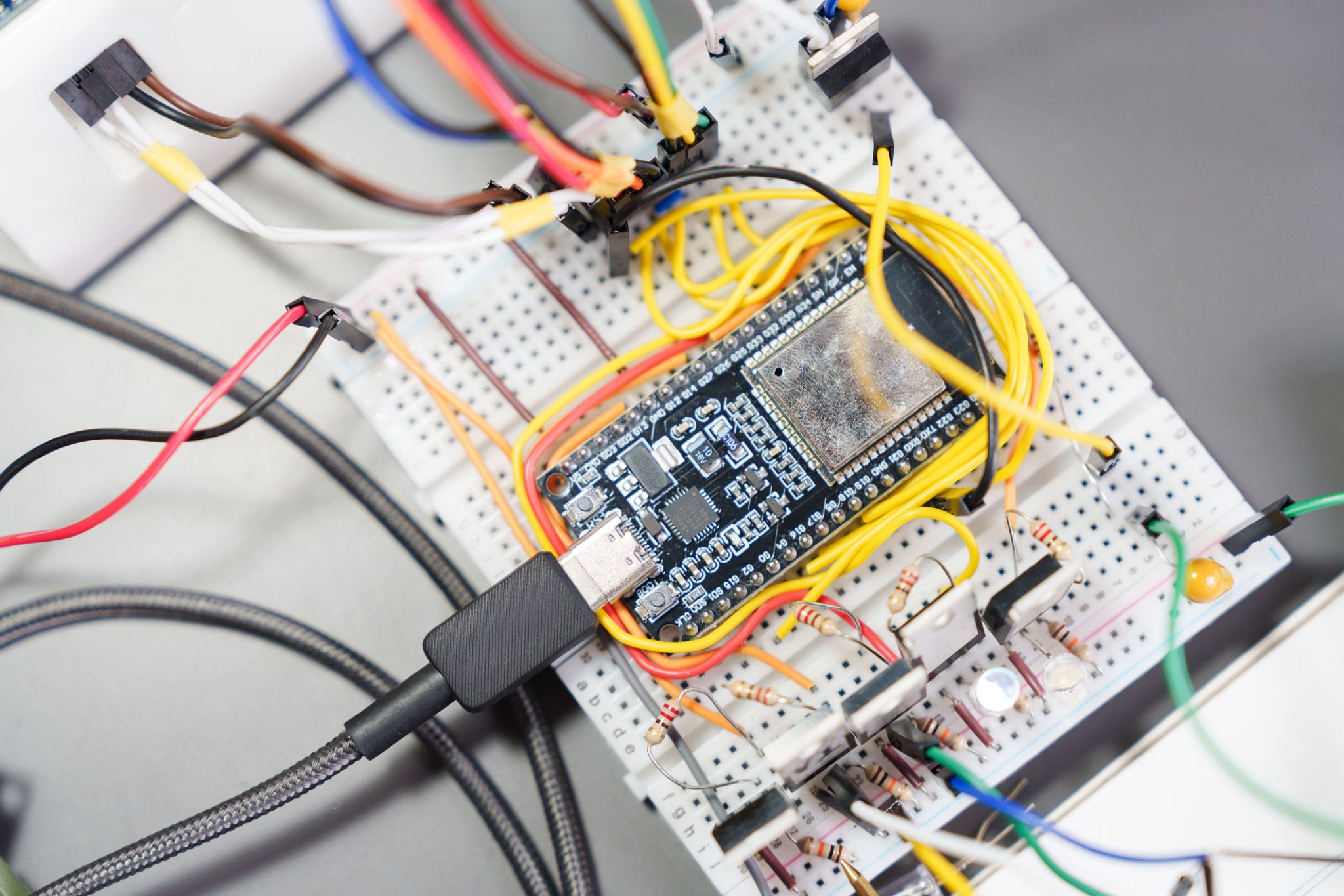
The Problem
When operating a domestic or semi-industrial central heating system controlled by legacy mechanical or cheap digital on-off (bang-bang) thermostats, users frequently experience severe temperature swings, excessive thermal hysteresis, and slow transient responses. The living space or loop fluid overheats past the target setpoint, followed by a long period of chilling before the boiler or circulation pump kicks back in.Specifically, the user sees erratic temperature fluctuations exceeding $\pm 3^\circ\text{C}$ to $\pm 5^\circ\text{C}$ around the target value. This happens during ambient weather shifts or rapid load changes. Users typically try adjusting mechanical bimetallic dials or replacing basic room thermostats with standard wireless relay switches, but these fail because they lack proportional integral derivative (PID) mathematical damping, resulting in perpetual system hunting and thermal fatigue on valves and burners.
Possible Causes
Bang-Bang Control Hysteresis: Binary ON/OFF logic lacks modulation capability, forcing the heating element or circulation pump to run at 100% capacity until overshooting the threshold.Sensor Placement Lag: Placing temperature sensors inside poorly ventilated enclosures or far from the actual heat exchange manifold introduces severe thermal inertia, delaying control loops.Lack of Derivative Damping: Without accounting for the rate of temperature change ($de/dt$), the system overshoots violently during rapid startup phases.Integral Windup Saturation: Unbounded error accumulation during long heating cycles causes the actuator to remain fully saturated long after the setpoint has been reached.
Tools and Components Needed
ESP32 NodeMCU Development Board (38-pin or standard dual-core module, 240 MHz).
DS18B20 Waterproof Digital Temperature Sensor (Stainless steel probe sleeve, 1-Wire protocol interface).
4.7k ohm Pull-up Resistor (1/4W metal film, required for the 1-Wire data line).
IRLR8259 logic-level N-channel MOSFET or Zero-Crossing Solid State Relay (SSR) (e.g., Fotek SSR-40DA) for safe power actuation.
External 5V / 2A Regulated Power Supply (To power the ESP32 and switching logic safely away from high-voltage noise).
Digital Multimeter (True RMS for voltage and continuity verification).
Soldering station, heat shrink tubing, and 22 AWG copper wiring.
Step-by-Step Solution
- Hardware Assembly and 1-Wire Bus Wiring: Connect the waterproof DS18B20 sensor to the ESP32. Wire the VCC pin of the sensor to 3V3, GND to GND, and DQ (Data) to GPIO 4. Solder a 4.7k ohm pull-up resistor between the DQ line and 3V3. Connect the control gate of the IRLR8259 MOSFET or the input trigger of the SSR to GPIO 16 (ACTUATOR_PWM_PIN) through a 220 ohm current-limiting resistor.
- Flashing the Closed-Loop PID Firmware: Open your development environment, install the DallasTemperature and OneWire libraries, and upload the following production-grade C++ script to your ESP32:
C++
#include <Arduino.h>
#include <OneWire.h>
#include <DallasTemperature.h>
const int ONE_WIRE_BUS = 4; // DS18B20 data line on GPIO 4
const int ACTUATOR_PWM_PIN = 16; // PWM output to MOSFET/SSR gate on GPIO 16
OneWire oneWire(ONE_WIRE_BUS);
DallasTemperature sensors(&oneWire);
// Tunable PID constants for thermal mass stability
double Kp = 20.0;
double Ki = 0.5;
double Kd = 4.0;
double setpoint = 45.0; // Target water temperature in degrees Celsius
double input, output, lastInput;
double errSum, lastErr;
unsigned long lastTime;
unsigned long sampleTime = 1000; // 1-second sample rate
void computePID() {
unsigned long now = millis();
unsigned long timeChange = (now - lastTime);
if (timeChange >= sampleTime) {
sensors.requestTemperatures();
input = sensors.getTempCByIndex(0);
if (input == DEVICE_DISCONNECTED_C) return; // Fault handling check
double error = setpoint - input;
// Anti-windup clamping to restrict integral accumulation
errSum += (error * timeChange);
if (errSum > 400) errSum = 400;
else if (errSum < -400) errSum = -400;
double dInput = (input - lastInput);
// Compute standard PID output equation
output = (Kp * error) + (Ki * errSum) - (Kd * dInput);
// Constrain output to 8-bit PWM duty cycle limits (0 to 255)
if (output < 0) output = 0;
if (output > 255) output = 255;
// Apply actuation signal
analogWrite(ACTUATOR_PWM_PIN, (int)output);
lastInput = input;
lastTime = now;
}
}
void setup() {
Serial.begin(115200);
sensors.begin();
pinMode(ACTUATOR_PWM_PIN, OUTPUT);
lastTime = millis();
}
void loop() {
computePID();
}
3. Calibration and Fine-Tuning of PID Gains: Power on the system and monitor serial output at 115200 baud. Observe the transient response. If the system oscillates continuously, reduce Kp by 20%. If the temperature rises too slowly without reaching the setpoint, increase Ki incrementally.
Images and Diagrams
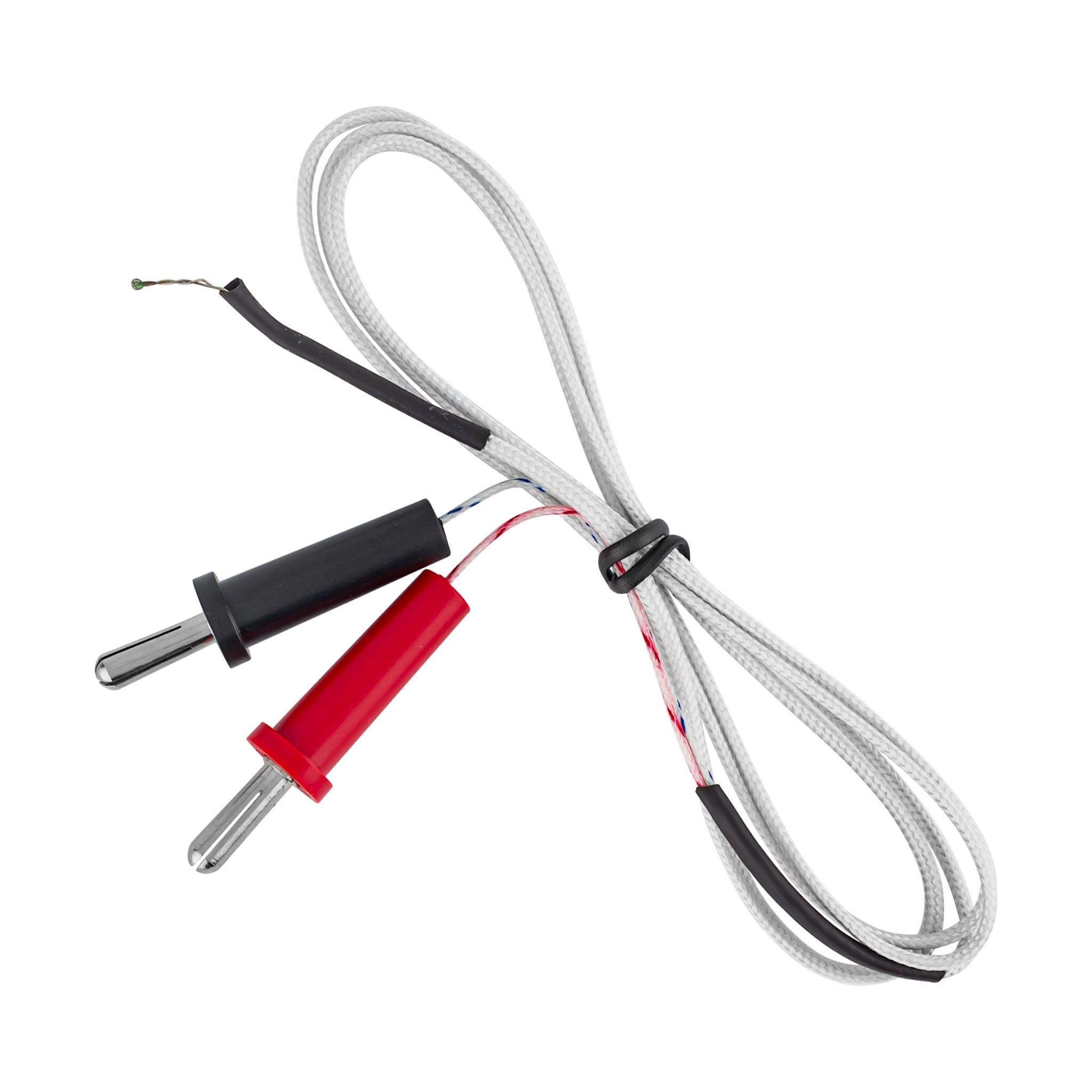
Figure 1: Waterproof DS18B20 Probe Sensor.
Common Mistakes
Omitting the 1-Wire Pull-Up Resistor: Forgetting the 4.7k ohm resistor between data and VCC results in a 85.00°C persistent reading or complete sensor communication failure.
Unshielded Wiring Near AC Mains: Running low-voltage sensor cables parallel to high-voltage 230V lines induces electromagnetic interference (EMI), causing erratic ADC/digital jumps. Always use twisted-pair or shielded cables.
Neglecting Anti-Windup Limits: Allowing the integral error term (errSum) to grow infinitely during long initial heat-up cycles causes massive, uncontrollable temperature overshoots.
Mains Voltage Isolation: When interfacing with 230V AC heating pumps or burner solenoids, always use properly rated optoisolated solid-state relays (SSRs) or electromechanical relays with complete physical galvanic isolation.Thermal Burns Hazard: Exercise extreme caution when attaching sensors or working near copper manifolds and heating pipes during active system operation.Fail-Safe Overheating Protection: Always install an independent, non-software mechanical thermal safety cutoff fuse in series with the actuator power supply to prevent runaway heating if the microcontroller freezes.How to Verify the FixVerify that sensor readings match a calibrated reference thermometer touching the same pipe surface within $\pm 0.5^\circ\text{C}$.Inspect the Serial Monitor to confirm that the PWM output duty cycle smoothly ramps down as the process variable approaches the target setpoint.Test a step response by introducing a temporary thermal load and confirming the loop recovers without ringing or sustained oscillation.Frequently Asked Questions### Can I monitor this heating controller remotely over Wi-Fi?Yes. Because the ESP32 features built-in Wi-Fi and Bluetooth capabilities, you can integrate a lightweight AsyncWebServer or connect the firmware to a Telegram Bot API (@Chauffage03_bot) to monitor temperatures and adjust the setpoint remotely.### Why use DS18B20 sensors instead of standard thermistors?DS18B20 sensors communicate digitally over the 1-Wire protocol, providing factory-calibrated 12-bit Celsius measurements directly without requiring complex analog-to-digital calibration curves or voltage divider math.
Comments